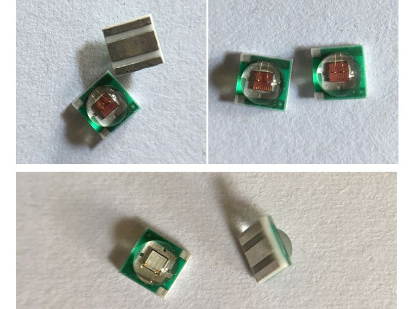
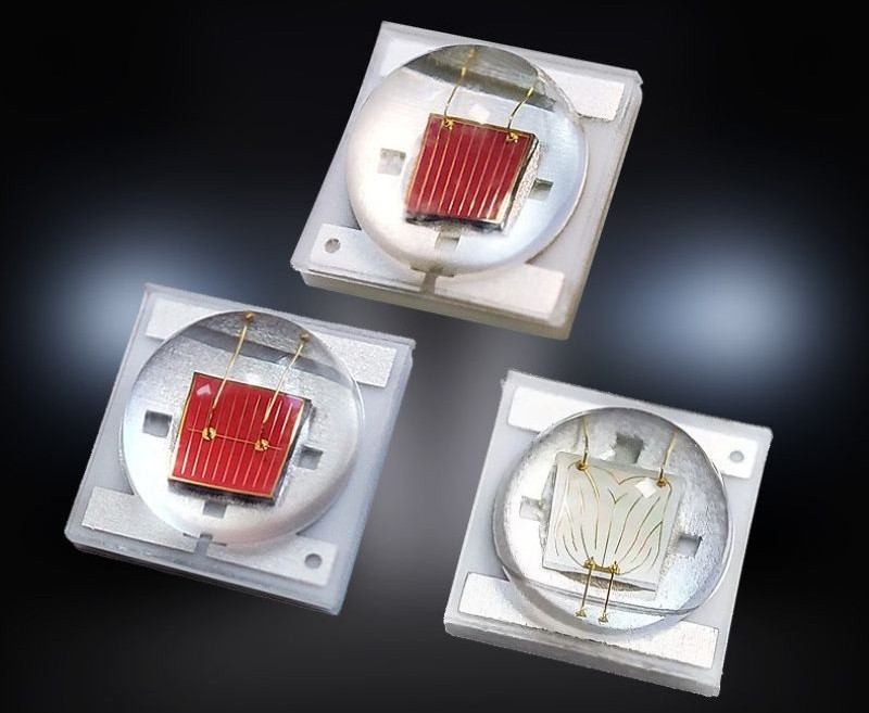
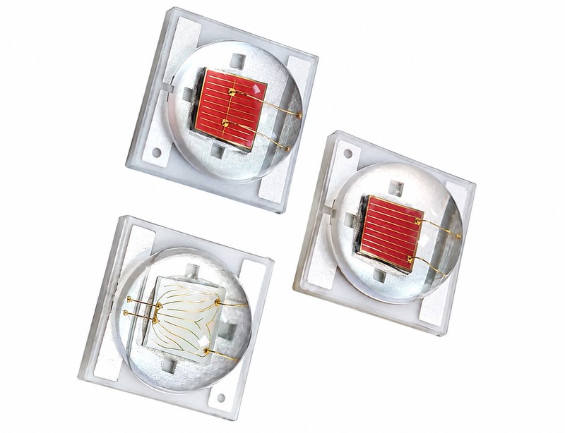
3535 LED 规格书
Ceramic SMD 3535 High Power LED — Full Specification
Model: 3535-CER-1W / 3W / 5W | Package: 3.5mm × 3.5mm Ceramic Substrate, SMD Surface Mount
Document Rev: A1 | Date: 2026-10-09 | Test Condition: Ta = 25°C, Tj = 25°C unless otherwise noted
1. Product Overview
3535 LED refers to a surface-mount LED with a package size of 3.5mm × 3.5mm. This package is highly compatible and can be designed as micro-power, medium-power, or high-power products depending on chip material, number of chips, substrate solution, and driving conditions. Common power ratings range from 0.05W to over 5W, and it is widely used in lighting, backlighting, indicators, RGB addressable lighting, UV curing, and other applications.
This specification covers the ceramic-substrate high-power range (1W / 3W / 5W), featuring an alumina (Al₂O₃) ceramic carrier with low thermal resistance and superior heat dissipation compared with EMC 3535 packages.
|
Model
|
3535-CER-1W / 3W / 5W
|
|
Package Dimension
|
3.5mm × 3.5mm Ceramic Substrate, SMD Surface Mount
|
|
Substrate
|
Al₂O₃ ceramic (AlN ceramic upgrade available for ultra-low Rth)
|
|
Document Rev / Date
|
A0 / 2026-10-09
|
2. Features
-
Alumina ceramic carrier, low thermal resistance, superior heat dissipation vs. EMC 3535.
-
Multiple power grades: 1W / 3W / 5W; custom 6W multi-chip available (limited reliability).
-
Full spectrum: White, visible monochrome, IR, UV, RGB / RGBW multi-chip.
-
Flip chip / wire-bond chip options; 99.99% gold wire.
-
Wide operating temperature range; high ESD protection.
-
RoHS, REACH compliant; MSL3 moisture sensitivity level.
-
Multiple beam angles: 60° / 90° / 120° / 140°.
3. Core Parameters
|
Parameter
|
Typical Range
|
Detail
|
|
Package size
|
3.5mm × 3.5mm
|
Normal surface-mount package
|
|
Height
|
1.3mm to 2.8mm
|
Varies via model
|
|
Forward voltage
|
1.8V to 3.8V
|
Lower for red, higher for blue, green, and white
|
|
Forward current
|
20mA to 1500mA
|
Some high-power models can go higher
|
|
Viewing angle
|
120° (normal)
|
Customizable to 60°, 90°, 140°
|
|
Luminous flux
|
Approx. 80 to 150lm for 1W white
|
Depends on CCT / CRI; high-power models can reach over 155lm
|
|
Operating temperature
|
-40℃ to +105℃
|
Industrial-grade range (solder pad temperature)
|
4. Power Levels
|
Power Level
|
Common Power
|
Typical Current
|
Common Applications
|
Parameter Features
|
|
Micro power
|
0.05W to 0.2W
|
20mA
|
Indicators, RGB decoration, addressable LEDs
|
Low current per channel, built-in IC available
|
|
Medium power
|
0.2W to 1W
|
150mA to 350mA
|
General lighting, backlighting, displays
|
Stable light efficiency, moderate cost
|
|
High power
|
1W to over 5W
|
350mA to 1500mA
|
Spotlights, streetlights, flashlights, UV curing
|
High heat dissipation requirements, ceramic substrate or copper lead frame
|
5. Absolute Maximum Ratings (Ta = 25°C)
|
Parameter
|
Symbol
|
1W
|
3W
|
5W
|
Unit
|
Remarks
|
|
DC Forward Current
|
I_F
|
350
|
700
|
1500
|
mA
|
Continuous rated
|
|
Peak Pulse Current
|
I_FP
|
500
|
1000
|
2000
|
mA
|
Duty ≤10%, pulse width ≤10ms
|
|
Power Dissipation
|
P_D
|
1.2
|
3.6
|
5.5
|
W
|
Max dissipation
|
|
Reverse Voltage
|
V_R
|
5
|
5
|
5
|
V
|
Not for reverse bias operation
|
|
Junction Temperature
|
T_J
|
125
|
125
|
125
|
°C
|
Absolute limit
|
|
Operating Temp. Range
|
T_OPR
|
-40 ~ +105
|
-40 ~ +105
|
-40 ~ +105
|
°C
|
Solder pad temperature
|
|
Storage Temp. Range
|
T_STG
|
-40 ~ +125
|
-40 ~ +125
|
-40 ~ +125
|
°C
|
Unassembled reel
|
|
Solder Reflow Temp.
|
T_SLD
|
260
|
260
|
260
|
°C
|
Max 10s
|
|
ESD (HBM)
|
ESD
|
8000
|
8000
|
8000
|
V
|
JEDEC JS-001
|
|
Thermal Resistance
|
Rth(j-p)
|
≤10
|
≤6
|
≤2.5
|
°C/W
|
Junction to pad
|
6. Electrical & Optical Characteristics
6.1 White Range (Mainstream for Lighting)
|
CCT
|
CRI
|
Test I_F
|
Vf Min
|
Vf Typ
|
Vf Max
|
Φv Min
|
Φv Typ
|
Unit
|
|
2700K
|
Ra80
|
350mA
|
2.9
|
3.1
|
3.4
|
100
|
120
|
lm
|
|
3000K
|
Ra80
|
350mA
|
2.9
|
3.1
|
3.4
|
110
|
130
|
lm
|
|
4000K
|
Ra80
|
350mA
|
2.9
|
3.1
|
3.4
|
120
|
140
|
lm
|
|
5000K
|
Ra80
|
350mA
|
2.9
|
3.1
|
3.4
|
125
|
145
|
lm
|
|
6000K
|
Ra70
|
350mA
|
2.9
|
3.1
|
3.4
|
130
|
150
|
lm
|
|
4000K
|
Ra90
|
700mA
|
3.0
|
3.2
|
3.5
|
220
|
250
|
lm
|
|
4000K
|
Ra80
|
1500mA
|
3.0
|
3.2
|
3.6
|
320
|
360
|
lm
|
Notes: Binning via Vf / Lumen / CCT; ANSI bin available for tight color consistency.
6.2 Monochrome LED
|
Color
|
Wavelength λd
|
Test I_F
|
Vf Typ
|
Vf Range
|
Radiant Flux / Luminous Flux
|
|
Deep Red
|
620~630nm
|
350mA
|
2.2V
|
2.0~2.4V
|
70~90 lm
|
|
Red
|
640~660nm
|
350mA
|
2.1V
|
2.0~2.4V
|
50~70 lm
|
|
Orange
|
600~610nm
|
350mA
|
2.3V
|
2.1~2.5V
|
80~100 lm
|
|
Green
|
520~530nm
|
350mA
|
3.1V
|
3.0~3.4V
|
90~110 lm
|
|
Royal Blue
|
450~460nm
|
350mA
|
3.2V
|
3.0~3.4V
|
1800~2200 mW
|
|
Ice Blue
|
490~500nm
|
350mA
|
3.1V
|
3.0~3.4V
|
60~80 lm
|
|
IR Infrared
|
850nm / 940nm
|
350mA
|
1.8V
|
1.6~2.0V
|
600~900 mW
|
|
UVA
|
365 / 385 / 395 / 405nm
|
1000mA
|
3.4V
|
3.2~3.8V
|
1200~1600 mW
|
6.3 RGB 3-in-1 3535
|
Channel
|
λd
|
I_F per Channel
|
Vf Typ
|
|
R
|
620~630nm
|
350mA
|
2.2V
|
|
G
|
520~530nm
|
350mA
|
3.1V
|
|
B
|
450~460nm
|
350mA
|
3.2V
|
RGBW 4-in-1: add white chip, 3000K / 4000K optional.
6.4 6V Dual-Chip Series (2 chips in series)
|
Parameter
|
Value
|
Remarks
|
|
Vf Typ
|
6.2V (5.8~6.4V)
|
2 chips in series
|
|
Rated I_F
|
700mA (3W) / 1000mA (5W)
|
For driver series connection design
|
7. Optical Properties
|
Item
|
Specification
|
|
Viewing Angle (2θ₁/₂)
|
60° / 90° / 120° / 140° (120° normal)
|
|
Radiation Pattern
|
Lambertian (normal dome lens)
|
|
Color Binning
|
3-step / 5-step / ANSI 7-step binning available
|
|
Color Shift
|
Vf decreases ~2mV/°C with rising junction temperature
|
8. Parameter Differences via Application Type
|
Type
|
Typical Power
|
Forward Current
|
Forward Voltage
|
Key Features
|
|
RGB addressable
|
0.05W to 0.2W
|
20mA per channel
|
3.5V to 5.5V
|
Built-in IC, single-wire cascade control
|
|
White lighting
|
1W to 5W
|
350mA to 1500mA
|
2.7V to 3.8V
|
High luminous efficiency, CRI 70/80/90, CCT 2580K to 7000K
|
|
UV ultraviolet
|
0.9W to over 3W
|
700mA to 1000mA
|
3.2V to 3.8V (UVA) / 3.6V to 7V (UVC)
|
Used for sterilization and curing, UVC wavelength 270 to 285nm
|
|
Ceramic substrate
|
1W to 5W
|
350mA to 1500mA
|
1.8V to 3.4V
|
Excellent heat dissipation, high reliability, suitable for harsh environments
|
9. Reliability Tests (Qualification)
|
Test Item
|
Condition
|
Acceptance
|
|
LM-80 Long Term Aging
|
Ta = 85°C, I_F rated, 6000hrs
|
L70 > 50,000hrs projected
|
|
High Temp Operating Life
|
85°C, rated current, 1000h
|
ΔΦv ≤10%, no dead lamp
|
|
Temperature Cycle
|
-40°C ↔ +85°C, 1000 cycles
|
No mechanical damage, ΔΦv ≤10%
|
|
High Temp Humidity
|
85°C / 85%RH, 1000h
|
ΔΦv ≤10%, no corrosion
|
|
Solder Heat Resistance
|
260°C, 10s reflow
|
No delamination
|
|
ESD Test
|
HBM 8kV
|
No electrical failure
|
10. Packing & Mechanical
|
Item
|
Specification
|
|
Tape & Reel
|
4000 pcs / reel
|
|
SMD Pad Layout
|
Normal 3535 footprint
|
|
Lens
|
Silicone dome lens; high transmittance, UV resistant
|
|
Substrate
|
Al₂O₃ ceramic; AlN ceramic upgrade for ultra-low Rth (optional)
|
11. Applications
-
Outdoor flood light, high bay, street light
-
Stage lighting, landscape RGB lighting
-
UV curing, IR sensing
-
Automotive auxiliary lamp
-
Retail display, spot light
-
Indoor lighting, commercial spotlights, streetlight modules, flashlights
-
Backlight displays, RGB addressable light strips
-
UV sterilization and curing, industrial equipment indicators
12. Selection Tips
Please confirm the light color and wavelength, target power and driving current, forward voltage range, viewing angle, heat dissipation conditions, and substrate material. Actual power is calculated as forward voltage multiplied via forward current. Heat dissipation conditions affect the maximum power that can be operated stably over the long term.
13. Design & Caution Notes
-
Constant current drive only; voltage source is prohibited. Vf drift with temperature will cause over-current and burn-out.
-
5W version requires sufficient thermal pad and heat sink; derate current when pad temperature > 70°C.
-
Peak pulse current only allowed under 10% duty cycle; continuous operation at peak current invalidates warranty.
-
LED is sensitive to reverse voltage; reverse bias > 5V will destroy chip.
-
MSL3: Moisture sensitive, bake required after reel opened over 168h.
-
Storage: Keep in dry packing, RH < 60%.
14. Certifications
RoHS, REACH compliant. LM-80 report available on request; UL file optional.