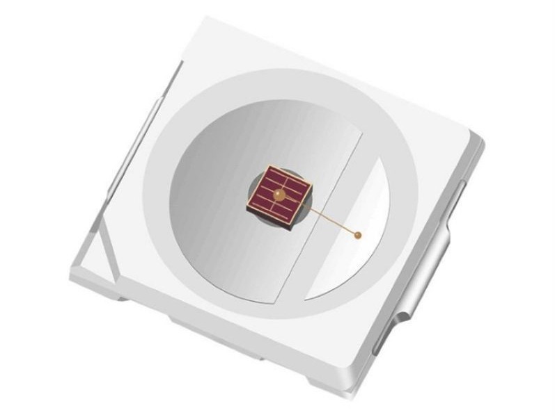
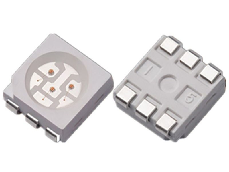
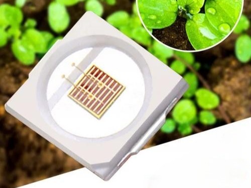
SMD LED 1W3030RCT Specification
SMD LED SPECIFICATION
|
Customer
|
|
Product Type
|
TOP LED
|
|
Customer Type
|
|
Type
|
1W3030RCT
|
|
Version NO
|
|
Product
|
1W3030
|
|
Research and Development Center
|
Customer (Stamp)
|
|
APPROVE
|
CHECK
|
DRAW
|
CONFIRM
|
Red 1W 3030 smd led Diode
Technical Data Sheet
Red 1W 3030 smd led Diode is mainly used as an electronic component for signal indication and lighting, and is widely used in various electronic products that use surface mount structures, such as household lighting, lamps, electrical switch indicators, mobile phone keyboard lights, automobile dashboard lighting, and this product is also widely used in various indoor and outdoor decorative lighting, monitoring and security products.
Features:
-
Emitting Color: Red
-
Material: InGaN
-
Encapsulation: Resin
-
Soldering methods: Pb-Free reflow soldering
-
High Luminous Intensity, Low Power Dissipation, good Reliability and Long Life
-
Complied With ROHS Directive
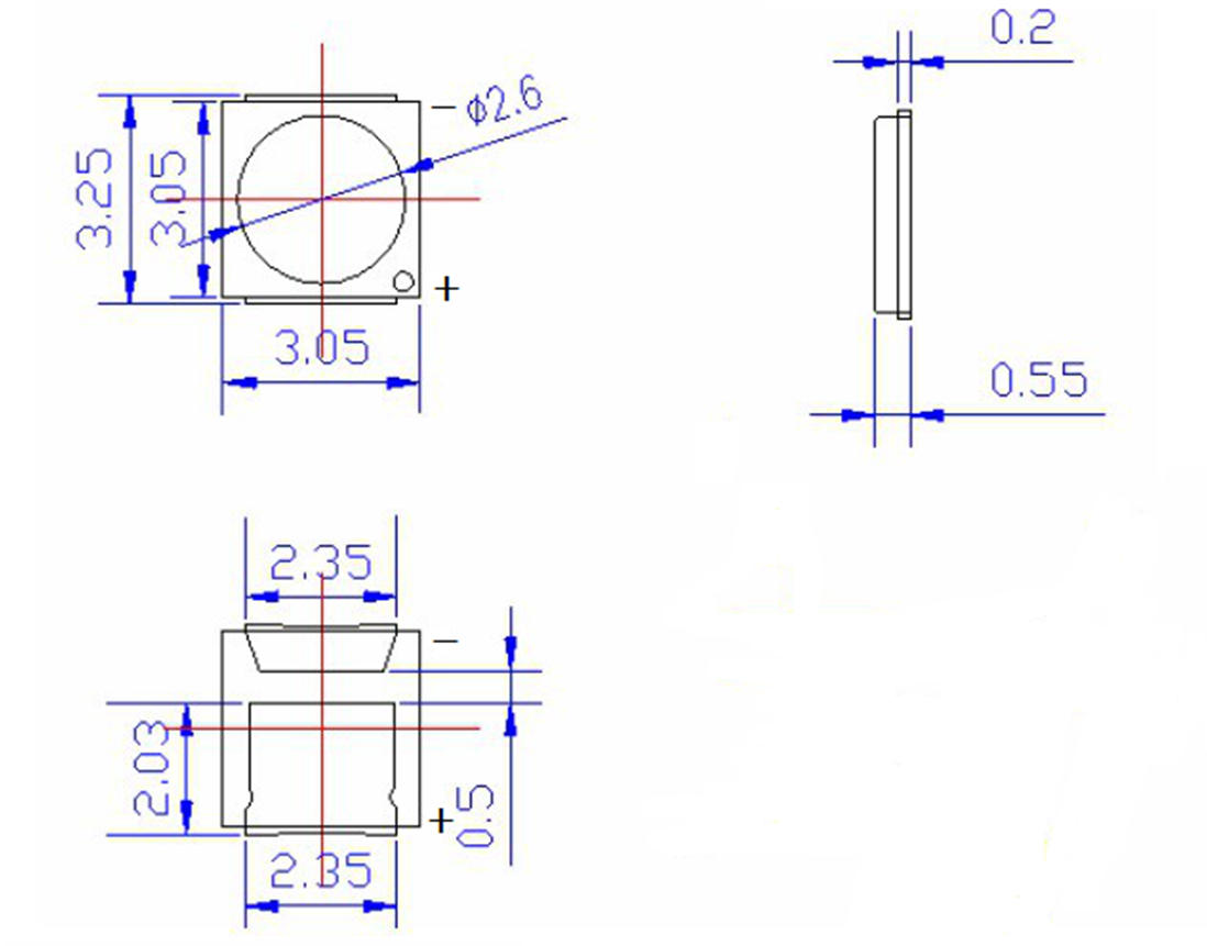
Outline Dimensions:
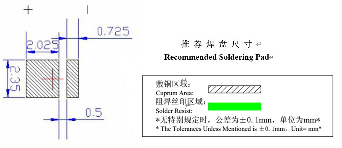
Electrical Characteristics
Absolute Maximum Ratings (Temperature 25 deg C)
|
Parameter
|
Symbol
|
Rating
|
Unit
|
|
Forward Current
|
IF
|
300
|
mA
|
|
Pulse Forward Current
|
IFP
|
450
|
mA
|
|
Power Dissipation
|
Pd
|
660
|
mW
|
|
Reverse Voltage
|
VR
|
5
|
V
|
|
Operating Temperature
|
Topr
|
minus 30 to plus 100 deg C
|
deg C
|
|
Storage Temperature
|
Tstg
|
minus 40 to plus 90 deg C
|
deg C
|
Note: Pulse width maximum 0.1 ms, Duty maximum 1 over 10
Electro-Optical Characteristics (Temperature 25 deg C)
|
Parameter
|
Symbol
|
Condition
|
Color
|
Min
|
Typ
|
Max
|
Unit
|
|
Luminous Intensity
|
IV
|
IF is 300 mA
|
R
|
22
|
not specified
|
30
|
lm
|
|
Dominant Wavelength
|
lambda d
|
IF is 300 mA
|
R
|
618
|
620
|
624
|
nm
|
|
Peak Wavelength
|
lambda p
|
IF is 300 mA
|
R
|
625
|
628
|
630
|
nm
|
|
Spectrum Bandwidth
|
Delta lambda
|
IF is 300 mA
|
R
|
not specified
|
20
|
not specified
|
nm
|
|
Forward Voltage
|
VF
|
IF is 300 mA
|
R
|
2.0
|
not specified
|
2.4
|
V
|
|
Reverse Current
|
IR
|
VR is 5 V
|
R
|
not specified
|
not specified
|
5
|
micro A
|
|
View Angle
|
2 Theta half
|
IF is 300 mA
|
R
|
not specified
|
120
|
not specified
|
deg
|
Typical Characteristic Curves
Wavelength Groups (Dominant Wavelength at IF 300 mA)
|
Wavelength Groups
|
Min (nm)
|
Max (nm)
|
|
A1
|
615
|
620
|
|
A2
|
620
|
625
|
Brightness Groups (IF 300 mA)
|
Brightness Groups
|
Min (lm)
|
Max (lm)
|
|
B1
|
20
|
25
|
|
B2
|
25
|
30
|
Note: The standard shipping format for serial types includes either a lower family group, an upper family group or a grouping of all individual brightness groups of 3 or 4 or 6 individual brightness groups. Individual brightness groups cannot be ordered.
Group Name on Label
Example: A2 to B2
Note: No packing unit or tape ever contains more than one group for each selection.
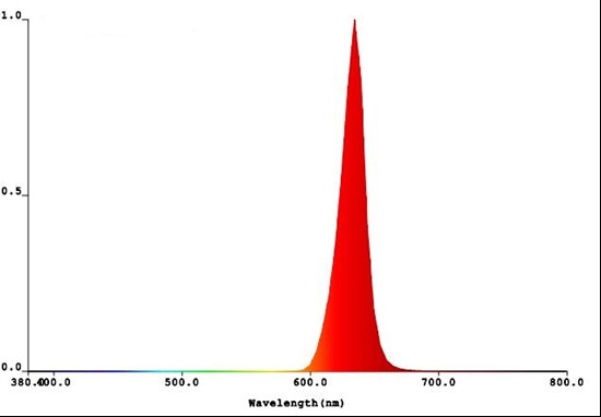
Relative Spectral Emission
V(lambda) is Standard eye response curve, Phi(rel) is f (lambda); TA is 25 deg C; IF is 300 mA
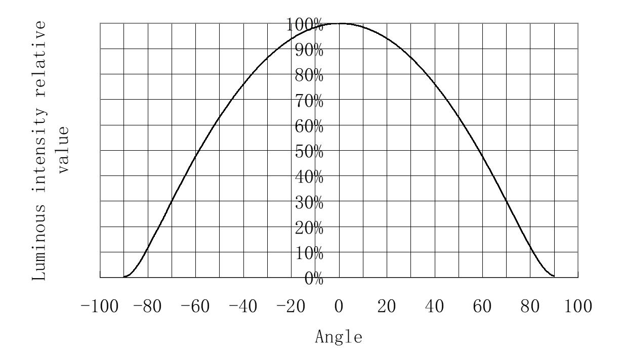
Radiation Characteristic Phi(rel) is f (phi); TA is 25 deg C
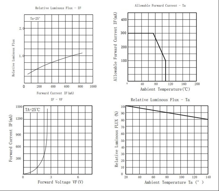
Typical optical characteristics curves. (Graphical data omitted)
Reliability Test Items And Conditions
|
Test Items
|
Reference
|
Test Conditions
|
Time
|
Quantity
|
Criterion
|
|
Thermal Shock
|
MIL-STD-202G
|
minus 40 deg C (30 min) to plus 100 deg C (30 min)
|
100 cycles
|
22
|
0 over 22
|
|
Temperature And Humidity Cyclic
|
JEITA ED-4701 200 203
|
minus 10 to plus 65 deg C, 0 percent to 90 percent RH, 24 hrs per cycle
|
10 cycles
|
22
|
0 over 22
|
|
High Temperature Storage
|
JEITA ED-4701 200 201
|
Ta is 100 deg C
|
1000 hrs
|
22
|
0 over 22
|
|
Low Temperature Storage
|
JEITA ED-4701 200 202
|
Ta is minus 35 deg C
|
1000 hrs
|
22
|
0 over 22
|
|
High Temperature High Humidity Storage
|
JEITA ED-4701 100 103
|
Ta is 80 deg C, RH is 90 percent
|
1000 hrs
|
22
|
0 over 22
|
|
High Temperature Life Test
|
JESD22-A108D
|
Ta is 80 deg C, IF is 250 mA
|
1000 hrs
|
22
|
0 over 22
|
|
Life Test
|
JESD22-A108D
|
Ta is 25 deg C, IF is 250 mA
|
1000 hrs
|
22
|
0 over 22
|
|
Resistance to Soldering Heat
|
JEITA ED-4701 300 301
|
Reflow Soldering
|
3 times
|
22
|
0 over 22
|
Criteria For Judging Damage
|
Items
|
Symbol
|
Test Conditions
|
Criteria For Judging Damage
|
|
Forward Voltage
|
VF
|
IF is 250 mA
|
greater than or equal to USL
|
|
Reverse Current
|
IR
|
VR is 5 V
|
greater than or equal to USL
|
|
Luminous Intensity
|
IV
|
IF is 250 mA
|
less than or equal to LSL
|
|
Resistance to Soldering Heat
|
|
|
Material without internal cracks, no material between stripped, no deaded light
|
USL means Upper Standard Level, LSL means Lower Standard Level
Packaging
Carrier Tape - Dimensions in mm, tolerance plus or minus 0.1 mm unless noted.
(Carrier tape drawing omitted)
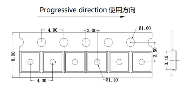
Notes: 1. All dimensions are in millimeters. 2. Tolerance is plus or minus 0.1 mm unless otherwise noted.
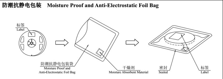
Keep away from water and moisture to protect the LEDs. The LEDs may be damaged if the boxes are dropped or receive a strong impact, so precautions must be taken.
Packaging (2) - Label Explanation
-
Part No: MH - Product Type
-
QTY: Quantity
-
LOT NO: Lot Number
-
IV: Luminous Intensity Range
-
lambda d: Wavelength Range
-
VF: Forward Voltage Range
-
IF: Testing Current
Guideline for Soldering
Hand Soldering: A soldering iron of less than 20 W is recommended. Keep the temperature under 300 deg C while soldering. Each terminal to go for less than 3 seconds and for one time only. Be careful because damage often starts at hand soldering.
Reflow Soldering: Use Pb-Free reflow soldering profile (graphical curve omitted). Reflow soldering should not be done more than one time. Stress on the LEDs should be avoided during heating. After soldering, do not handle before temperature drops to room temperature.
Cleaning: It is recommended to use alcohol for cleaning after soldering, at maximum 30 deg C for 3 minutes or maximum 50 deg C for 30 seconds. Before using other solvents, verify they do not damage the encapsulation. Ultrasonic cleaning is effective but power should not exceed 300 W; pre-test to avoid damage.
Note: This general guideline may not apply to all PCB designs and soldering equipment. Specialize based on actual conditions.
Precautions
Storage: Moisture-proof and anti-electrostatic package with desiccant. Unopened products have a shelf life of one year at maximum 30 deg C and maximum 60 percent RH. After opening, store at maximum 30 deg C and maximum 10 percent RH, and solder within 168 hours (7 days). Recommended workshop condition: maximum 30 deg C, maximum 60 percent RH. If desiccant expires or storage exceeded, bake at 60 plus or minus 5 deg C for 24 hours.
Design Consideration: Current through each LED must not exceed absolute maximum rating. Use protective resistors; slight voltage shift may cause overcurrent. Recommended circuit A (regulates current per LED) rather than circuit B (constant voltage may cause imbalance due to VF variation). Thermal design is critical - heat generation reduces brightness and shifts color.
Others: Avoid touching encapsulant directly to prevent contamination and static damage. Excessive force (especially when heated) may cause die breakage or wire deformation. Do not scratch the epoxy resin surface. When using tweezers, do not hold by the resin.
Safety Advice For Human Eyes: Do not view the light emitting center directly, especially high-intensity LEDs, as strong light may harm eyes.